
We intend to create this shared space and close the gap between drilling and geoscience workflows.

Trajectory planning is one of the first steps in any preliminary well design life cycle. For a long time, directional drilling companies used isolated methodologies without any subsurface integration to generate trajectory planning. This siloed workflow posed severe challenges while simulating more realistic scenarios of multi-well pads for unconventional onshore development.
The typical scenario involves heavily populated fields of vertical wells and new complex horizontal well trajectories where the need for skilled well planners is very high. As our Well Planning software became popular with geologists, the tool was also exposed to drilling engineers. Today, geoscientists and drilling engineers work closely during trajectory planning and this demands a more connected and collaborative environment.
With the launch of the new and improved Well Planning software as part of the latest DecisionSpace® 365 Geosciences Suite, we intend to create this shared space and close the gap between drilling and geoscience workflows. And since we believe in giving you the freedom to choose what works best for you – our innovative software is available both on the cloud as well as an on-premise solution, as part of DecisionSpace 10ep.
Well Planning is a collaborative well planning software, and what sets it apart from other well planning tools is that it was designed with the multidisciplinary asset teams in mind.
From a visual approach, this software connects the surface with the subsurface by defining an imaginary line between both. It considers all the surface requirements and restrictions to provide a surface location, accounts for the pre-defined subsurface model including geological targets and hazards. Finally, it considers the mechanical restrictions of the technology that will be used to construct the well to ensure highest safety and profitability.
The Well Planning software is extensively used during the planning phase of unconventional development fields, especially to optimize the directional drilling trajectories design process. With the rise in unconventional onshore development, the adoption and implementation of this end-to-end well planning solution has also rapidly sped up in the last few years.
As trajectory planning activity became more collaborative and multi-disciplinary, we started getting requests for feature upgrades and additions to simplify and improve the overall process. Let’s go through some of these new additions.
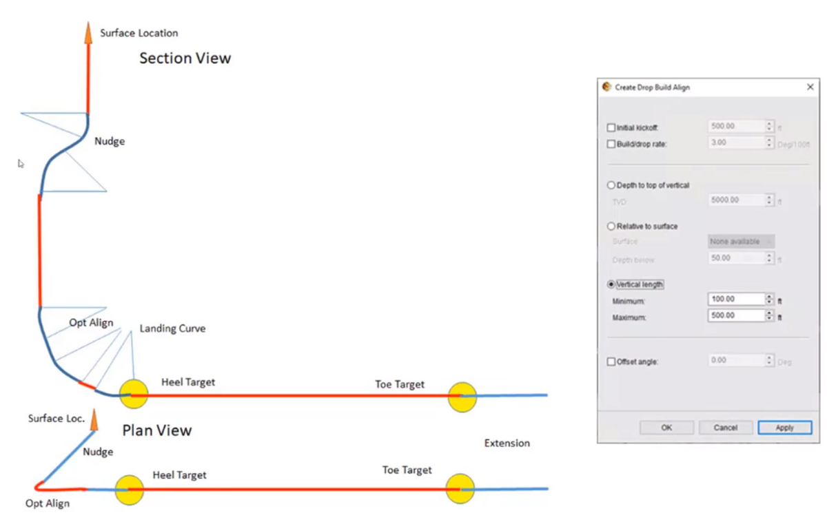
This key feature represents one of the horizontal well trajectories that is commonly used in unconventional developments. Often referred to as S+J shape, this trajectory profile is a directional driller friendly build for horizontal well plan. With this trajectory, the planning engineers will be able to move planned targets and the well spacing will be automatically calculated. The planning engineer can also adjust the trajectory nudge (initial kick-off depth and build/drop rate), then drop to vertical to the point for the final build that is aligned to the heel target and the horizontal direction.
This directional drilling requirement for unconventional wells provides the means to simulate a more simplistic and realistic directional drilling work. This in turn allows the operations team to concentrate on depth control to hit the target horizon with accuracy during the execution phase.
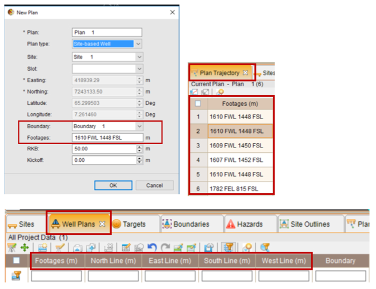
Footage Calls are a requirment in land lease based well planning. They are a way of describing surveyed positions of sites, wellhead and/or proposed target locations relative to specific boundaries. These measured locations are defined as the X and Y distances from a selected lease corner.
The Well Planning software automatically calculates the footage calls when at least one existing boundary is defined for the well planning scenario in the preferences section. The relevant object (site, plan, or target) must be located within such a boundary, although the boundary and footage calls can be used to initialize a specific location. The footage calls can also be directly entered and edited to match survey location that may not have Lat/Long or XY coordinates.
The footages show up in the following places for sites, well plans, targets and plan trajectory tables. If any of them is created using the “Create New” option, in addition to Easting/Northing and Lat/Lon, there will be an option to "See/Select/Specify" a boundary and footages. The footages will be in the form “999 FWL 999 FSL”, where the measurements and lines will be referenced to the two nearest lines. Ideally, this will work wellfor a North-South oriented square boundary but can also work for other shapes.
While editing, if an object has calls and is within a specific boundary, and the user changes those calls, the object will be moved to reflect those calls. If a different boundary is selected, the object will be moved to that same call location within the new boundary.
If the object was not within a boundary and is selected, the object will be assigned a default footage call of “5 FWL 5 FNL” and will be placed in the upper left corner of the boundary (if possible).
The ‘Well Plans’ table also has optional individual footage for each cardinal directions, i.e. the North, East, South and West lines. These will indicate how close the nearest target is to each of those lines. This has also been covered in ‘Plan Target Movers’ as part of S+J well feature. The ‘Plan Trajectory’ table shows footage for each row and any change in plan updates all rows.
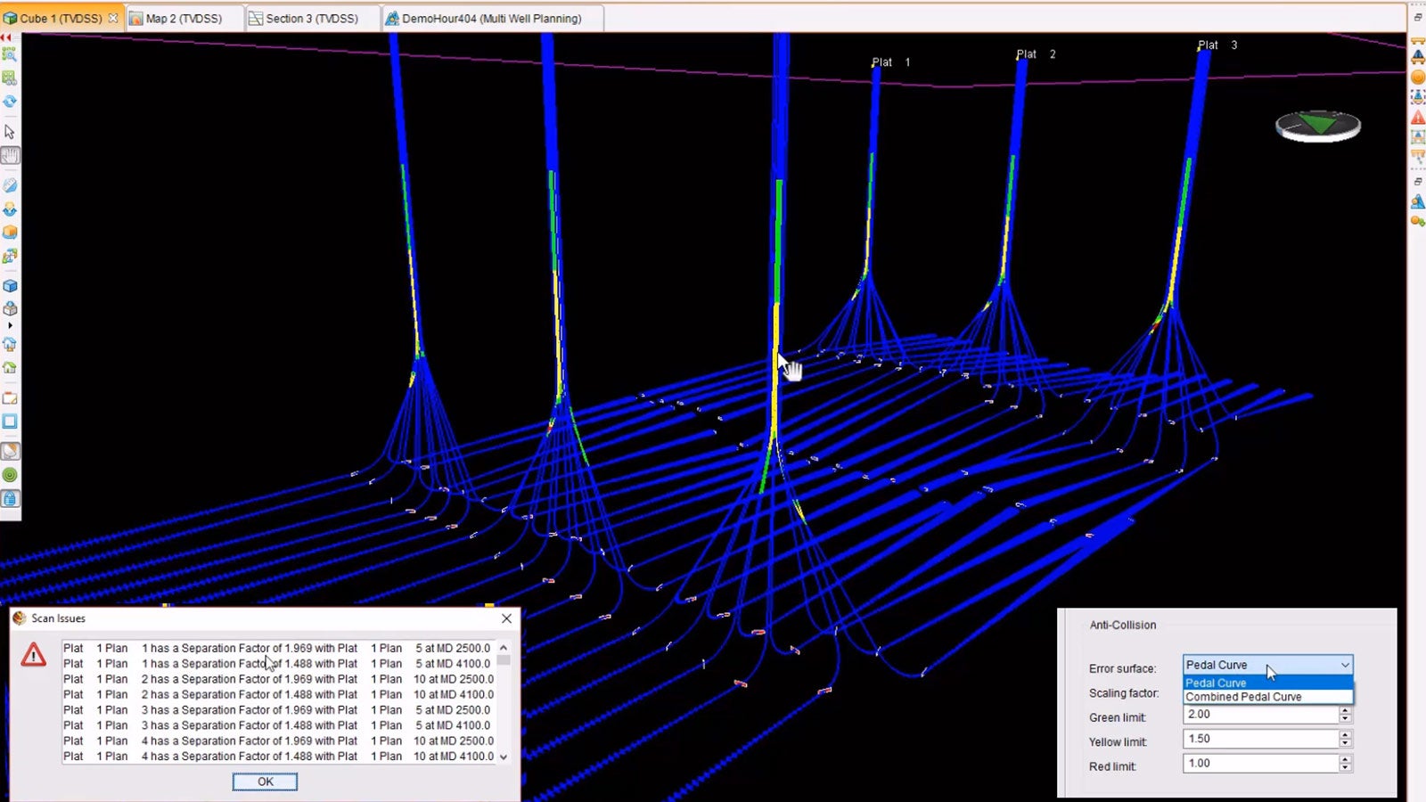
In our latest release, the previously used ‘Cone of Error’ model has been replaced by industry standard anti-collision recommendations. The anti-collision capability within the Well Planning software now supports the ‘Pedal Curve’ and the ‘Combined Pedal Curve’ error models. In addition, it features separation factor calculation, provides three warning levels that are graphically represented in a well path color scheme and provides a minimum separation scan summary result. This field summary anti-collision feature is based on ISCWSA standards.
The Well Planning software allows users to define initial anti-collision preferences for a specific scenario. Depending on this configuration, the application will provide the desired calculations and visual results. However, the user must be aware that successful results rely on the quality and completeness of data. The correct survey tool errors must be assigned to the planned trajectories and the offset wells considered in the analysis. Also, users must include all the drilled wells with potential collision risk.
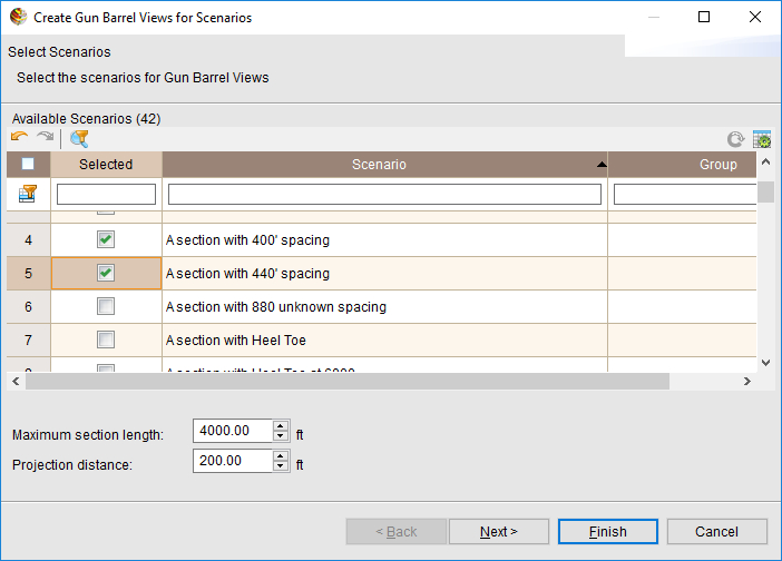
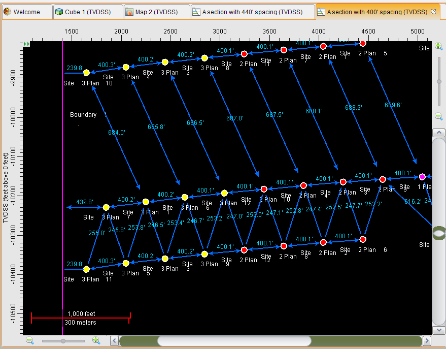
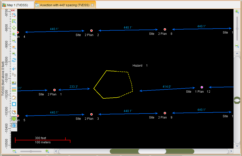
Gun barrel is a special section view with a User Interface (UI) component that allows you to select well planning scenarios and set of parameters to be displayed within a gun barrel view.
This UI is presented in the form of a wizard. Once the scenarios are selected, it will open each one, compute an appropriate Line of Section (LOS) for it, and open a new section view with that LOS.
The drawing module of the gun barrel adds specific graphics to the view. This is a regular section view and can display all the regular data, such as surfaces, frameworks, seismic, faults, etc. The user can add the session data that they wish to display and set the display parameters appropriately. A unique aspect of the gun barrel view is that the boundaries are displayed as vertical lines where the LOS crosses them.
The gun barrel graphics and annotations are dynamic and decisions about what and how to display them are generally made in screen pixels rather than absolute units. This means that an arrow might turn into a brace if you zoom in or it might transform into a line if you zoom out. Or it might disappear altogether if you zoom out far enough.
Each scenario plan that crosses the LOS is used as a point in the gun barrel view. Well lists from the OpenWorks® software that are in the session and within the scenario will be taken into consideration. The annotation of distances between points will be subject to limits on distance and angle boundaries being crossed by the LOS are also considered points.
However, they only have the X component, so they get the same Y value as any plan point they are being annotated against. The annotation is done for all the visible plans within a scenario.
If multiple scenarios are being displayed in the same section view, they will all get annotated, but only the differences between the points in the same scenario will be shown. Also note that both the separation annotations and the filled circle (and label) are made at the last point where each horizontal plan crosses the LOS. Labels and distance annotations are also created for other plans that are displayed, but do not cross the LOS in gun barrel fashion. Distances from Hazards and Boundaries are also annotated.
The latest release of the Well Planning software within the Geosciences Suite features extensive upgrades and enhancements to help you keep pace with the rapid evolution of unconventional workflows in the last few years.
The enhancements will help assets teams to collaborate effectively with drilling engineers, completions engineers, mapping, and land/regulatory contributors during the preliminary planning phase of a field development. We have also extended the existing automation workflows to include detailed design tasks required by drilling engineers.
A commonly used trajectory profile for horizontal wells can now be applied to multiple directional plans. All the footage calls that must be complied based on lease boundaries are automatically calculated. ISCWSA standards have been implemented in a commonly used anti-collision analysis workflow. And although the gun barrel feature was mainly driven by geoscientists, it also helps the drilling team to have a clearer view of well proximity issues to be avoided.
In summary, we believe the latest edition of the Well Planning software is a big step forward in closing the cross-domain workflow gap between drilling and geoscience.
To learn more about these new capabilities, register for the Closing the Breach Between Drilling and Geoscience in Unconventional Onshore Development webinar today.
Expert: Maria E. French | Product Manager, Compass™ And Decisionspace® Well Planning
Jerry Codling, Dan Colvin, Gordon Young, Humayun Pervez, Shang Zhang, Gareth Braund, Grant Ohlms, Nayan Patel