 Search
 Search

Anisotropic Inversion helps define the Lithology of Apparent Oil-Water Contact
Download PDFMature Fields

Understand undulating OWC in a trilateral well

Norway

EarthStar® ultra-deep resistivity service with 3D inversion:
A complex, OWC in a trilateral well, identified by seismic data before drilling and confirmed with the EarthStar® ultra-deep resistivity service from Halliburton, proved to the operator that reservoir complexity is not easily understood if investigated via conventional tools and inversion of resistivity alone. Advances in three-dimensional (3D) electromagnetic (EM) inversion technology in the EarthStar service allow mapping of both resistivity and anisotropy (the vertical to horizontal resistivity ratio) data.
Anisotropy is used to differentiate between low resistivity, water-filled sand units marked by low anisotropy ratios, and low resistivity shale units that exhibit high anisotropy. Gaining insight into anisotropy helped the operator understand the undulating fluid contact issue for maximizing the value of this asset.
The OWC morphology was identified before drilling commenced using seismic and offset log data. As expected, it clearly showed considerable total vertical depth (TVD) variation along the wellbore. However, this is difficult to explain in a permeable sand environment. In some places, the depth shift created a very steep, near-vertical, angle with the OWC. The operator required a better explanation for why the water did not move laterally in these zones, smoothing out the fluid contact.
The EarthStar 3D ultra-deep resistivity service was recommended to measure both resistivity and anisotropy. Water-flooded sands and low resistivity shales can show similar resistivity values. Since water-flooded sands are isotropic while shales are anisotropic due to their laminated nature, the anisotropic inversion from the EarthStar service provides a way to differentiate water-flooded sands from shales, and to reveal the lithology of low resistivity zones.

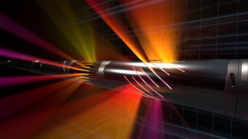
Ultra-deep resistivity service mapping reservoir and fluid boundaries up to 225 feet from the wellbore.